Thermal Oil Heating Systems: 8 Design Checks Before You Specify a System
Thermal oil heating systems look simple on a one-line diagram: a heater, a pump, a circulation loop and process users. The failures happen in the details, and the details are exactly what a component-level quotation rarely shows. This guide walks through the eight checks that decide whether a thermal oil system runs for decades or burns through its fluid, pump seals and budget in the first year.
Why Thermal Oil Replaces Steam in Medium-Temperature Processes
Thermal oil systems operate as a liquid loop, typically between 150°C and 350°C at near-atmospheric pressure, where steam systems would need very high pressures for the same temperature. That pressure difference removes the need for licensed boiler operators, reduces insulation and safety overhead, and gives finer temperature control at the process user.

The trade-off is that the fluid itself becomes the working asset. Thermal oil degrades with temperature, oxidation and time, and once the fluid degrades, the whole loop suffers: carbon deposits on heater surfaces, pump seals wear, and control response drifts.
A system that treats the oil as an afterthought is a system that fails early. The broader principles of heater selection are covered in our guia de seleção de aquecedor de imersão.
Verificar 1: Heat Duty and the Sizing Basis
The heater must be sized on the peak simultaneous heat load of all process users, not the average, and not the nameplate of the largest single user. A common failure is sizing on average load, then adding a process line later, which pushes the heater beyond its design duty and accelerates fluid degradation.
When we size a system, we ask for the full list of process users, their operating schedules and their individual duties. The result is a heater duty that covers the worst realistic hour, with a control margin that does not force the heater to run at its ceiling all day.
Verificar 2: Fluid Selection and Temperature Limits
The thermal fluid defines the operating window. Every fluid has a maximum bulk temperature and a maximum film temperature, and the film temperature at the heater surface is almost always higher than the bulk temperature. Specifying a fluid for its bulk limit while the film runs hotter is how thermal oil cokes.
Fluid selection should also match the process temperature range you actually need. Running a 350°C-rated fluid at 180°C for years is inefficient and over-expensive; running a 280°C fluid at 320°C is a reliability error. Confirm the fluid’s recommended operating band against your process users before you commit.
Verificar 3: Circulation Rate and Film Temperature Control
The circulation pump must move enough oil that the temperature rise across the heater stays within the fluid’s safe band. Too little circulation raises the film temperature and starts carbon formation on the heater surface; too much wastes pumping energy and wears the system.
The design figure that matters is the temperature rise across the heater at full duty. A well-designed system keeps that rise within the fluid manufacturer’s recommendation, and the pump curve should be checked against the actual loop pressure drop, not assumed. We calculate both before quoting, because the pump is the component buyers most often under-specify.
Verificar 4: The Expansion and Venting System
Thermal oil expands with temperature, and the expansion tank is what absorbs that volume change. Undersized expansion capacity causes pressure spikes and fluid loss; a tank that is open to atmosphere when the system runs above the fluid’s flash point is a fire hazard. The expansion and venting arrangement is a safety system as much as a mechanical one.
The layout also matters: the expansion line should connect at the pump suction, run without pockets where vapor can collect, and be sized for the expected expansion volume at the highest operating temperature. These are the details that show up in a good GA drawing and are invisible in a component price list.
Verificar 5: Heater Element Design and Watt Density
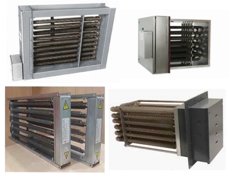
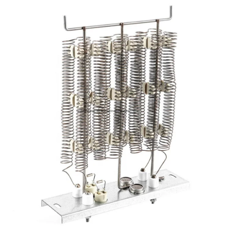
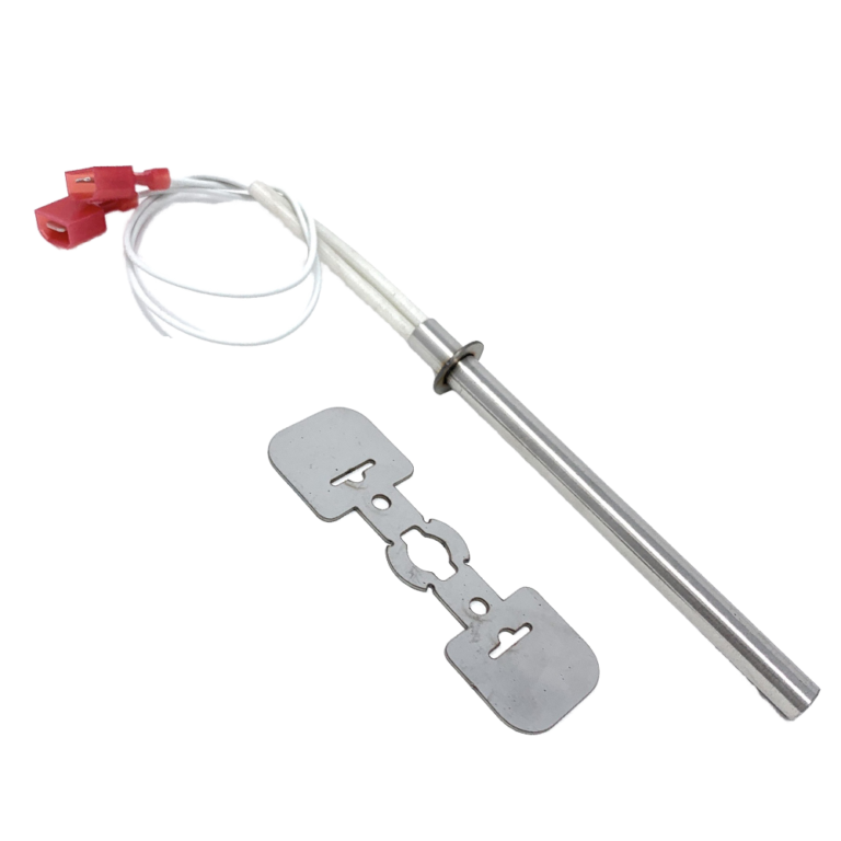
In an electric thermal oil system, the immersion heater elements are where the fluid meets the heat. Densidade de watts, the watts per square centimeter of element surface, decides the film temperature and therefore the fluid’s life. Too high a watt density means the oil next to the element overheats, forms carbon, and the element eventually fails.
For thermal oil service, we specify watt densities conservatively and design the element bundle so the oil flows past every surface without dead zones. Element geometry, sheath material and the flow pattern around the bundle are engineering decisions, and they are the difference between a heater that needs element changes every year and one that runs for a decade. The calculation method is explained in our guia de cálculo de densidade de watts.
Verificar 6: Control, Monitoring and Protection Logic
A thermal oil system needs more than a thermostat. The control system should manage heater output against return temperature, protect against overtemperature at the film level, and shut down safely on low flow, high pressure or pump failure. These interlocks are what prevent the coking and burnout events that dominate thermal oil failures.
Monitoring the oil itself is part of the same discipline. Regular sampling for degradation products, viscosity and flash point tells you when the fluid is approaching its limit, so you replace the oil before it replaces your heater. A system without a fluid sampling schedule has no way to see the failure coming.
Verificar 7: Piping, Insulation and Pressure Drop
The circulation loop must be routed to avoid pockets, dead legs and high pressure drop. Every dead leg is a place where oil stagnates, degrades and eventually forms sludge, and every unnecessary restriction adds pump work and heat loss. The piping layout is a first-order design decision, not a site convenience.
Insulation protects both energy and fluid: uninsulated lines lose heat, and heat loss forces the heater to work harder and the oil to cycle hotter than intended. Confirm the insulation specification matches the operating temperature class of the fluid.
Verificar 8: Maintenance Access and Documentation
The best thermal oil system is the one your maintenance team can actually service. Element bundles need to be removable, filters need to be reachable, and the pump and expansion tank need clear access. A design that saves space by burying components is a design that makes every future service event more expensive.
Documentation matters equally. The system should come with a P&ID, a GA drawing, the pump curve and the fluid specification, and your team should have a written startup, shutdown and sampling procedure. If the supplier cannot hand over these documents, the system is not finished.
Lista de verificação de auditoria de fornecedor: 6 Documents to Request Before You Commit
Before you award a thermal oil heating system contract, request these six documents. Each one verifies a design decision rather than a sales claim:
- 1. Heat duty calculation showing the peak simultaneous load and the sizing basis.
- 2. Pump curve matched against the calculated loop pressure drop and the required circulation rate.
- 3. Element watt density calculation with the resulting film temperature against the fluid’s limit.
- 4. Expansion and venting arrangement drawing with the expansion volume calculation.
- 5. P&ID showing the full loop, instrumentation and protection interlocks.
- 6. Fluid specification and recommended operating band, matched to your process temperature range.
A supplier who cannot produce these documents is asking you to buy a system on component prices, with the engineering left to you. In our experience, the audit takes an afternoon and removes most of the risk from the purchase.

Perguntas frequentes: Thermal Oil Heating Systems
What is the main advantage of a thermal oil heating system over steam?
Thermal oil delivers temperatures up to around 350°C at near-atmospheric pressure, avoiding the high-pressure steam infrastructure and its operating and safety overhead, while giving finer temperature control at the process user.
How do I size a thermal oil heater?
Size it on the peak simultaneous heat load of all process users, not the average and not the largest single nameplate. Include operating schedules and planned additions, and keep a control margin that avoids running the heater at its ceiling.
Why does watt density matter in thermal oil heaters?
Watt density decides the film temperature at the element surface. Excessive watt density overheats the oil film, forms carbon, degrades the fluid and shortens element life. Conservative watt density with good flow around the bundle protects both.
How often should thermal oil be replaced?
There is no fixed interval; replacement depends on operating temperature, hours and fluid condition. Regular sampling for viscosity, degradation products and flash point tells you when the fluid is approaching its limit.
What causes thermal oil to coke?
The main causes are film temperatures above the fluid’s limit, low circulation, oxidation through a poorly designed venting system and operating the fluid beyond its recommended band. Each is preventable at the design stage.
Contate-nos
Specifying a thermal oil heating system and want the sizing and circulation calculations done properly? Send us your process users and temperature requirements, and we will provide the heat duty calculation, pump curve and element watt density data alongside your quotation.
Consulte o JIELI THERMAL thermal oil heater selection guide for an independent overview of system selection fundamentals.