If you have ever encountered rapid element burnout or chamber contamination in a thermal vacuum system, you know the frustration of managing heat without air. La bonne nouvelle: mastering vacuum environment heating requires understanding radiation heat transfer mechanics, material outgassing limits, and precise surface emissivity matching.
Table des matières
Why Does Heat Transfer in Vacuum Rely Exclusively on Thermal Radiation?
Inside an evacuated chamber below 10⁻³ mbar, the mean free path of gas molecules exceeds chamber dimensions. Because convective gas currents cannot form without ambient air, heat transfer between the heating element and target workload occurs almost entirely through electromagnetic radiation.
According to the Stefan-Boltzmann law, radiant heat transfer scales with the fourth power of absolute temperature. Par conséquent, a slight increase in element sheath temperature dramatically accelerates net radiant flux toward colder chamber walls and target components.
In standard atmospheric heating, convective air circulation naturally dissipates surface heat away from the sheath. Without convective cooling, industrial vacuum environment heating requires derating element surface watt density to prevent internal nickel-chromium coil overheating and catastrophic sheath rupture.

What Outgassing and Material Compatibility Challenges Arise in Vacuum Chambers?
Operating electric heaters under deep vacuum conditions exposes materials to high vapor pressures and thermal volatilization. Common industrial metals containing zinc, cadmium, or lead sublime quickly at elevated temperatures, depositing conductive films onto chamber sight glasses and sensitive optical sensors.
Insulation materials must also be selected with extreme care to avoid releasing trapped moisture and volatile organic binders. High-purity sintered alumina ceramics and vacuum-fired fused quartz are required to maintain insulation resistance while eliminating hydrocarbon outgassing.
At Vanorm, notre 40+ years of electrical heating manufacturing expertise ensures all vacuum components undergo ultrasonic degreasing and vacuum pre-baking. Applying certified vacuum environment heating assemblies prevents batch contamination in semiconductor wafer processing and optical coating deposition systems.
How Does Surface Emissivity and View Factor Impact Heating Uniformity?
Radiant heating efficiency depends directly on the surface emissivity (ε) of the emitter and the geometric view factor between surfaces. Polished metallic sheaths reflect substantial radiant energy, whereas specialized oxidized or black ceramic coatings achieve emissivity values above 0.85 for maximum heat transfer.
Geometric view factors determine the proportion of radiant energy leaving the heater that directly intercepts the target surface. Multi-layer radiant heat shields constructed from polished stainless steel or molybdenum are positioned around the heating zone to reflect stray radiation back toward the workload.
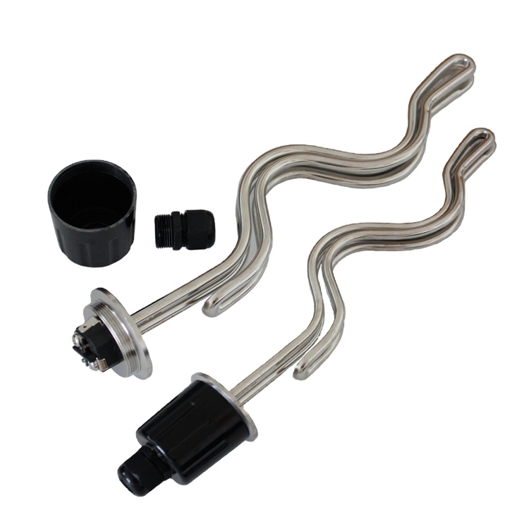
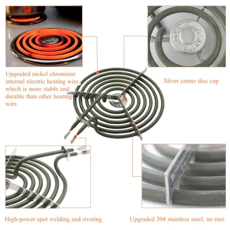
Dans notre pratique de fabrication, we engineer custom tubular heating arrays with calculated element spacing and curvature. Properly configured vacuum environment heating ensures uniform temperature distribution across delicate substrates without creating localized hot spots or thermal shadow zones.

Why Are Hermetic Electrical Feedthroughs Critical for Vacuum Heating Safety?
Delivering high-amperage electrical power into a sealed vacuum chamber requires hermetically sealed ceramic-to-metal feedthrough flanges. These specialized vacuum penetrations utilize brazed high-alumina insulators to provide mechanical rigidity, electrical isolation, and ultra-low helium leak rates.
Under intermediate vacuum pressures between 0.1 mbar and 10 mbar, electrical circuits become susceptible to glow discharge according to Paschen’s law. Maintaining adequate conductor spacing and dielectric encapsulation prevents electrical arcing between high-voltage terminals and grounded chamber walls.
En outre, heating elements undergo significant thermal expansion during thermal ramp-up cycles. Our engineering team incorporates flexible ceramic-insulated lead wires and expansion loops to prevent mechanical stress from fracturing brittle ceramic feedthrough seals during rapid heating sequences.
How Do Common Heating Element Materials Compare in Vacuum Applications?
| Element Material | Max Vacuum Temp (°C) | Outgassing Profile | Typical Vacuum Application | Thermal Expansion Rate |
|---|---|---|---|---|
| Incoloy 800 / Inconel 600 | 850°C | Low after bakeout | Thermal processing & degassing ovens | 14.4 µm/m·K (Moderate) |
| High-Purity FeCrAl Alloys | 1150°C | Ultra-low (oxidized) | Semiconductor substrate bakeout | 15.0 µm/m·K (Haut) |
| Molybdène / Tantalum | 1600°C – 2000°C | Near-zero in high vacuum | Vacuum sintering & métallurgie | 5.1 µm/m·K (Low) |
| Quartz Infrared Emitters | 900°C | Zero hydrocarbon trace | Thin-film solar & optical coating | 0.5 µm/m·K (Extremely Low) |
For verified material outgassing rates and volatile condensable material testing protocols in aerospace environments, review the screening data from NASA Outgassing Data for Spacecraft Materials. Using tested materials guarantees low contamination in high-vacuum chambers.
To evaluate complementary heating calculations and element designs, explore our guide de calcul de la densité de watt, notre ceramic vs metallic heating elements guide, et notre custom OEM heating element manufacturing process. These technical resources provide comprehensive engineering insight for demanding thermal applications.
Liste de contrôle d'audit des fournisseurs: 5 Documents à demander avant de signer un bon de commande
- Vacuum Outgassing and Material Purity Test Report: Certification confirming total mass loss (TML) and collected volatile condensable material (CVCM) limits comply with strict contamination standards.
- Helium Mass Spectrometer Leak Detection Certificate: Factory test report verifying hermetic feedthrough and sheath weld integrity with helium leak rates lower than 1×10⁻⁹ mbar·l/s.
- Dielectric Withstand and Paschen Curve Discharge Verification: High-voltage breakdown test records confirming electrical safety across intermediate pressure and deep vacuum operating ranges.
- Surface Emissivity and Thermal Radiation Modeling Report: Engineering calculations demonstrating radiant power distribution, view factor coverage, and sheath temperature limits.
- Thermal Shock and Expansion Cycling Validation: Test evidence proving the heating assembly withstands repeated rapid thermal cycles without micro-cracking or conductor deformation.
Deploying high-reliability vacuum environment heating requires strict supplier verification before final equipment assembly. Demanding certified quality documentation protects expensive vacuum pumps, prevents wafer contamination, and guarantees continuous production uptime in demanding thermal environments.
Foire aux questions
Q: Why do heating elements burn out faster in vacuum than in ambient air?
In a vacuum, the absence of convective gas molecules removes the primary cooling mechanism that protects element sheaths at normal atmospheric pressure. Without convective dissipation, internal resistance wire temperatures rise significantly higher for the same electrical load, causing accelerated thermal degradation if surface watt density is not derated.
Q: How do engineers prevent electrical arcing in intermediate vacuum?
According to Paschen’s law, gas breakdown voltage drops to a minimum in rough vacuum regimes between 0.1 mbar and 10 mbar where remaining gas molecules ionize easily. At Vanorm, our engineering team specifies extended creepage distances, ceramic insulating beads, and hermetically potted terminal geometries to eliminate arcing hazards.
Q: What sheath materials are best suited for high-temperature vacuum furnaces?
For temperatures up to 850°C, Incoloy 800 and Inconel 600 sheaths provide excellent structural integrity and low outgassing after vacuum degreasing. For operating temperatures exceeding 1100°C, refractory metals such as molybdenum, tantale, or specialized quartz infrared emitters are recommended to avoid metallic vaporization.
Q: What key parameters must be provided when requesting custom vacuum environment heating elements?
Specify your operating chamber pressure, maximum target substrate temperature, available electrical voltage and phase, chamber dimensional envelope, substrate material emissivity, and cycle ramp-up speed. Providing these specifications enables our engineering team to design an optimized radiant heating configuration.
For custom vacuum environment heating design support, share your operating vacuum level, temperature envelope, chamber dimensions, and substrate specifications with our engineering team. We will review your application requirements to deliver an optimized heating solution for your thermal system.